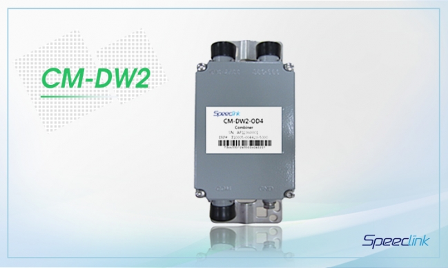
Outdoor Dual Band Combiner
CM-DW2-ODxG, CM-DW2D-ODxG (x=1, 2, 3 or 4, Preconfigured DC-pass)
Band 1:1710-1880MHz Band 2:1920-2170MHz
 |
Co-siting purpose for feeder sharing |
 |
Built with optional DC bypass, to be used with Tower Mounted Amplifiers and AISG devices |
 |
High isolation-minimizes interference |
 |
High power handling and low loss – maximizes system performance |
 |
Built-in lightning protection |
 |
Available as a single unit or double units |
 Electrical Specifications
|
Parameters / Specifications
|
Pass Band Frequency Range (MHz)
|
|
1710-1880
|
1920-2170
|
|
Insertion Loss (dB)
|
≤0.3
|
|
Isolation between Ports (dB)
|
≥50
|
|
Return Loss (dB)
|
≥20
|
|
Maximum Input Power per Port (W)
|
250
|
|
Intermodulation Products (dBc)
|
≤-155@2x43dBm
|
|
Impedance (Ω)
|
50
|
 Mechanical Specifications
|
Parameters
|
Specifications
|
|
Dimensions, LxWxH (excluding connectors) (mm) / (in)
|
Single Unit
|
210x124x61 / 7.6x4.9x2.4
|
|
Double Units
|
210x124x124 / 7.6x4.9x4.9
|
|
Weight (including connectors) (kg) / (lb)
|
Single Unit
|
1.9 / 4.2
|
|
Double Units
|
3.9 / 8.6
|
|
Color
|
Light Grey
|
|
RF Connectors
|
7/16 DIN-Female
|
|
Mounting
|
Pole (clamps included for Ф35-125mm pole) or Wall Mounted
|
|
Operating Temperature Range (oC)
|
-40 to +65
|
|
Operational Humidity (%)
|
≤95
|
|
Environmental Class
|
IP66
|
|
Shipping Dimensions, LxWxH (mm) / (in)
|
Single Unit
|
415x200x130 / 16.3x7.9x5.1
|
|
Double Units
|
415x200x195 / 16.3x7.9x7.7
|
|
Shipping Weight (kg) / (lb)
|
Single Unit
|
2.9 / 6.3
|
|
Double Units
|
5.4 / 11.9
|
|
Lightning Protection
|
Comply with IEC 61000-4-5; 8kA, 8/20ms
|
 Ordering Information
|
Single Unit Model Number
|
Double Unit Model Number
|
DC Bypass Optional
|
|
CM-DW2-OD1G
|
CM-DW2D-OD1G
|
No DC Bypass
|
|
CM-DW2-OD2G
|
CM-DW2D-OD2G
|
DC Bypass @1710-1880
|
|
CM-DW2-OD3G
|
CM-DW2D-OD3G
|
DC Bypass @1920-2170
|
|
CM-DW2-OD4G
|
CM-DW2D-OD4G
|
Full DC Bypass
|
 Block Diagram

[ Example: View of Single Units CM-DW2-OD4G ]
